5. Connecting the Hardware
This document explains how to connect the various BL602 boards.
5.1. Pine64 BL602 EVB ver 1.1
5.1.1. Serial
The USB-C connector provides power and a serial adapter.
Connect the board to the computer using the USB-C port.
LED2 should light up red when connected.
When loading programs the jumper on IO8 should be set to cover IO8 and H.
When running programs the jumper on IO8 should be set to cover IO8 and L.
The RESET button can be used after changing the jumper setting to reset the device without repowering it.
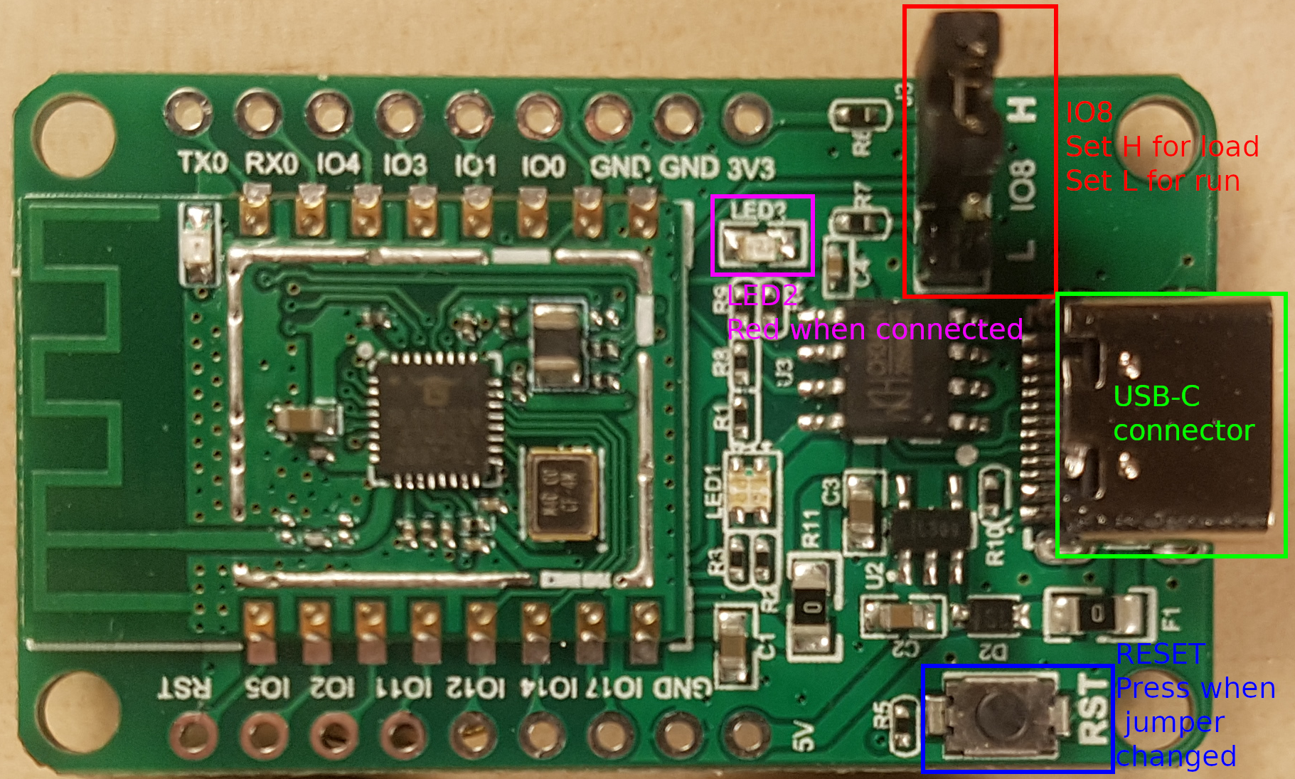
Pine64 BL602 EVB ver 1.1 board. IO8 jumper, LED2, the RESET button and the USB-C connection have been highlighted.
5.1.2. JTAG
See the article by Lee Lup Yuen.
5.2. Pine64 Pinenut-01S
The Pinenut-01S USB Programmer provides a serial connection through a USB-A connector. It is not possible to connect the Pinenut-01S serial connection through USB easily without the programmer.
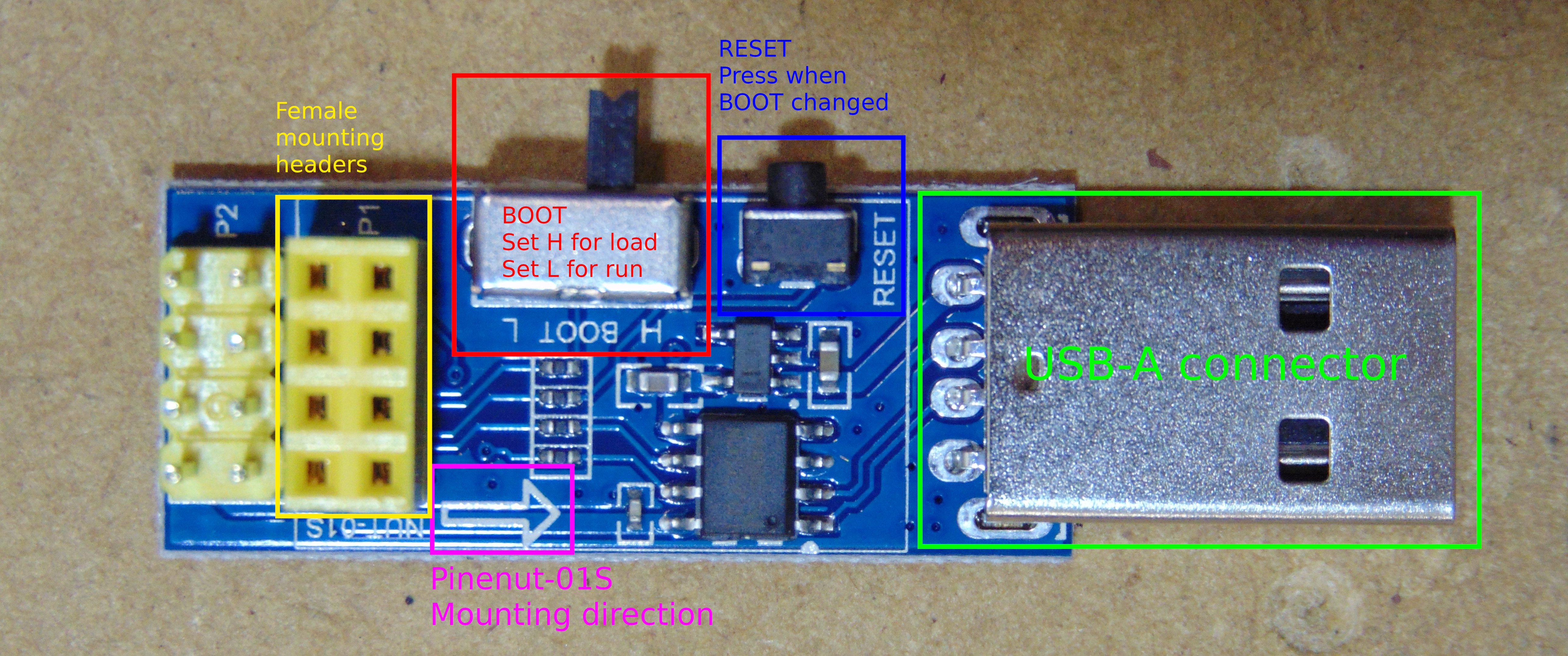
Pine64 Pinenut-01S Programmer. BOOT jumper, the RESET button, the NUT-01S mounting direction, the Pinenut-01S female mounting headers and the USB-A connection have been highlighted.
The Pinenut-01S must be mounted facing the correct way. The arrow on the programmer shows the direction the board should be mounted. An arrow has been added to the Pinenut-01S image and both arrows should point the same way when mounting.
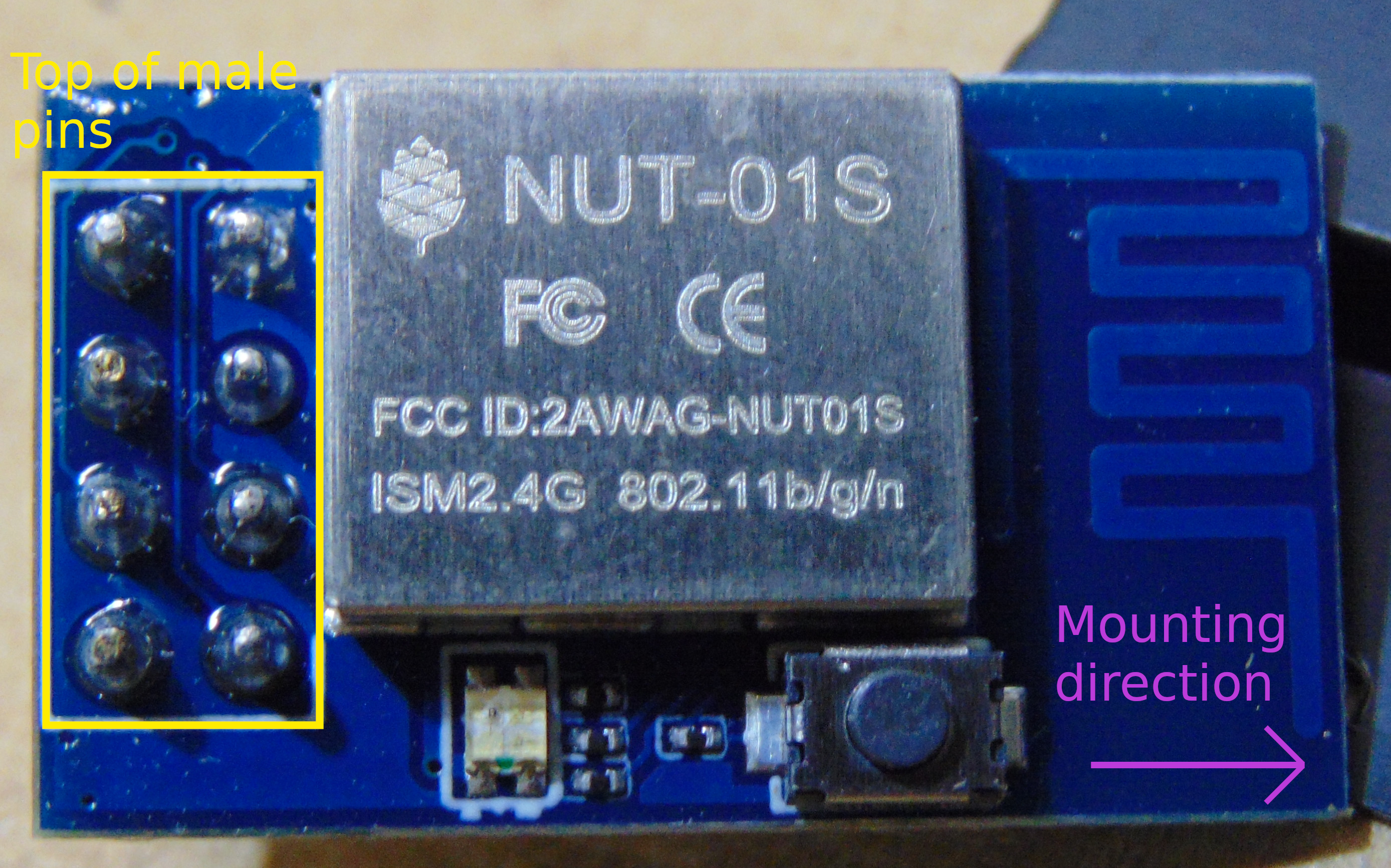
Pine64 Pinenut-01S. Mounting direction and top of male mounting headers have been highlighted.
When loading programs BOOT should be set to H.
When running programs BOOT should be set to L.
The RESET button on the programmer can be used after changing the jumper setting to reset the device without repowering it.
Pine64 Pinenut-01S correctly mounted on the programmer.
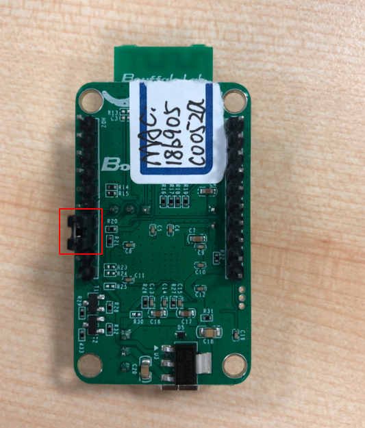
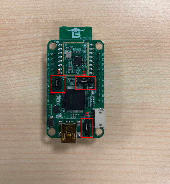
5.3. Boufallo Lab BL602 Dev Module
Notice: This section was included in the original documentation and in all likelyhood the board is not available anywhere. The text and images here are preserved for completeness sake.
This picture shows the front of the module. Connect the pins in position 1, 2 and 3 with jumper caps.
This picture shows the back of the module. Connect the header pin IO8 to LOW.